Amplifier output impedance and damping factor: what the specs actually mean

Every amplifier spec sheet lists a damping factor somewhere. Usually it's a big number on a solid-state integrated — 200, 500, sometimes over 1,000. Valve amps list something much smaller, sometimes in the single digits. Class D amps vary wildly depending on whether the output filter is inside or outside the feedback loop. And almost nobody explains what any of it actually means for your speakers, in your room.
So let me have a crack at that.
What output impedance actually is
An amplifier's output impedance is the source impedance it presents to the speaker terminals. Think of it as a small resistor in series between the amplifier's ideal voltage source and whatever you've plugged in. A perfect voltage amplifier would have zero output impedance — it would maintain exactly the same voltage regardless of what load you hang off it. Real amplifiers have some non-zero value, and that value matters.
Damping factor is just a restatement of the same thing. It's defined as the nominal speaker impedance divided by the amplifier's output impedance. If your amp has an output impedance of 0.1 ohms and you're driving an 8-ohm speaker, the damping factor is 80. If the output impedance is 0.04 ohms, it's 200. Higher damping factor = lower output impedance = closer to that ideal voltage source. The two specs are two ways of describing one underlying measurement.
The reason this matters is that a loudspeaker's impedance is not flat. It varies dramatically with frequency — a speaker nominally rated at 8 ohms might swing from 4 ohms in the bass to 25 ohms or more at its mechanical resonance. When the amplifier's output impedance forms a voltage divider with the speaker's impedance, any variation in speaker impedance creates a variation in the voltage actually delivered. That's a frequency-response error baked in by the amp/speaker interface.
Where valve amplifiers stand
Valve amplifiers almost always use an output transformer to match the high-impedance anode circuit of the output tubes to a speaker-friendly impedance. That transformer, plus the relatively modest amount of global feedback most valve designs use, results in output impedances that are typically between 0.5 and 4 ohms. Translating to damping factor: a valve amp driving an 8-ohm speaker at 1 ohm output impedance has a damping factor of 8. Some single-ended triode (SET) designs come in even lower.
That's not automatically a problem, but it does mean the speaker's impedance curve will shape the frequency response more than it would with a solid-state amp. A speaker with a generous impedance peak at resonance — say, 20 ohms at 50Hz — will receive a slight bass lift when driven from a high-impedance source. Some listeners find this pleasant. Some speaker designers account for it explicitly; they voice the speaker assuming a non-zero source impedance. Others don't, and the pairing sounds thick or wooly at the bottom.
The honest answer is that valve amplifiers and speakers need to be matched more carefully than solid-state and speakers. This is one reason why experienced valve enthusiasts tend to be fussy about speaker choice in a way that solid-state users often aren't. It's not folklore — it's physics.
Solid-state: why the spec floor matters more than the ceiling
Conventional solid-state amplifiers — bipolar or MOSFET output stages with moderate-to-high global feedback — routinely achieve output impedances below 0.1 ohms. Damping factors of 100 to 500 are common at 1kHz. At these levels the amplifier is close enough to a pure voltage source that the speaker's impedance variations have negligible effect on frequency response. The voltage divider error is tiny.
Here's where I'll push back slightly on a common audiophile position: above a damping factor of roughly 50–100, the audible benefit of further improvement becomes vanishingly small. The difference in bass control between a damping factor of 200 and 800 is measurable on a test bench and essentially inaudible in a real system, especially once you factor in the impedance of the speaker cable between the amp and the woofer. A metre of typical 2.5mm² cable adds perhaps 0.02 ohms each way — which at 4-ohm nominal load is already eating into whatever advantage your 1,000-damping-factor amplifier had over a 300-damping-factor one.
I'll admit I got wrapped up in chasing high damping factor numbers for longer than I should have. The spec is useful as a floor check — you want it reasonably high — but it stops being a meaningful differentiator well before the numbers manufacturers like to advertise.
Class D: a more complicated picture
Class D amplifiers use a switching output stage followed by a low-pass filter to reconstruct the audio signal from a high-frequency pulse train. Their output impedance behaviour depends heavily on whether the feedback loop closes around the output filter or before it.
Older Class D designs without output-filter feedback can have output impedance that rises significantly with frequency. At 20Hz they might measure 0.1 ohms; at 20kHz the same amplifier might be 2 ohms or more. That rising impedance interacts with the speaker's impedance curve across the audio band, not just at resonance. Some early Class D amps had a characteristic thinness or edge at the top end that traced back exactly to this mechanism.
Modern Class D designs — the better implementations from brands like Purifi, Hypex nCore, and others — close the feedback loop after the output filter, which dramatically flattens the output impedance across the full audio band. These amplifiers can achieve output impedance behaviour comparable to good solid-state designs. The topology has genuinely improved. If you're evaluating a Class D amp, ask specifically whether it uses post-filter feedback, or look for distortion-vs-load measurements that reveal how much the performance changes between 8 and 4 ohm loads.
The cable in the room you forgot to account for
Speaker cable resistance is a practical limit on achievable damping factor at the woofer terminal. This is worth thinking about more carefully than most buyers do.
Take a 4-metre run of modest 1.5mm² copper cable (common in older Australian homes and not unusual in a compact lounge room on, say, Brougham Street in Geelong or a terrace on Newtown's King Street). That cable has roughly 0.05 ohms per metre per conductor, so a 4-metre run each way is around 0.4 ohms total resistance. If your 8-ohm speaker and 500-damping-factor amplifier (output impedance ~0.016 ohms) are connected via that cable, the effective damping factor at the speaker terminal drops to about 17. Not catastrophic, but the amplifier's headline spec is now largely irrelevant.
Upgrading to 4mm² cable halves the resistance. Keeping runs short matters more than the amplifier's headline damping factor, in many practical situations. This is one place where cable quality genuinely does make a difference — not because of exotic metallurgy or dielectric geometry, but because cross-sectional area and length determine resistance, full stop.
For more on where cable spending actually shifts the needle, our piece on the best streaming amplifiers and all-in-one systems touches on the system-level view of where cost is best applied.
Matching amplifier topology to speaker impedance
Speaker sensitivity and impedance specs were covered in our KEF LS50 Meta review (check price) in passing, but the matching question deserves more direct treatment here.
The practical takeaway is this: speakers with benign, high, and relatively flat impedance curves are the most tolerant of amplifier output impedance. A speaker that stays above 6 ohms across the audio band with a modest impedance peak at resonance will work fine with a valve amp of moderate output impedance, assuming the sensitivity is adequate for the power on offer.
Speakers with aggressive impedance dips — 2 to 3 ohms in the bass, common in some British standmounts and some planar-magnetic designs — demand a low-output-impedance amplifier. With a high-output-impedance amp, those dips cause audible bass attenuation and can cause the amp to run warm or clip at lower levels than you'd expect. If you're running something like the Bowers & Wilkins 705 S3 (check price), which dips below 4 ohms in the midbass, pair it with something with a comfortable current reserve and a decent damping factor. A low-powered valve amp is a risky choice unless you've heard the specific pairing.
The Focal Kanta No.2 (check price) is an interesting case — nominally 8 ohms but with a known impedance phase swing that can stress high-output-impedance amps. It was designed to work with high-current solid-state, and it shows.
How to read the spec sheet when shopping
A few things worth checking when you're comparing amplifiers on paper.
First, look at whether the damping factor is specified at 1kHz or 100Hz or simply "audio frequency". Output impedance in many solid-state amps rises a little at frequency extremes, and some manufacturers cherry-pick the measurement frequency. A damping factor measured at 1kHz flatters most designs; measured at 20Hz or 10kHz it can be lower.
Second, check whether the spec is measured at the amplifier binding posts or "at the speaker terminal" (the latter sometimes accounts for an assumed cable length). The former is more honest and more consistent.
Third, for valve amplifiers, check if the output impedance is specified per output transformer tap. A valve amp with taps for 4-ohm and 8-ohm loads will have different effective output impedance at each tap. Using the 8-ohm tap on a 4-ohm speaker doubles the effective output impedance seen by that speaker. Use the right tap — it matters more on valve amps than almost any other matching consideration.
If you want to go further with matching considerations beyond the spec sheet, our overview of the best DACs and network streamers covers the source-side of the chain, and thinking about the full signal path is worth doing before you buy anything.
The bottom line on big damping factor numbers
Damping factor above about 50 is largely theoretical in real-world systems because cable resistance and speaker crossover impedance dilute the benefit before it reaches the driver. What you want from a solid-state amp is an output impedance low enough that speaker impedance swings don't cause audible response errors — and most competent solid-state designs achieve this comfortably.
For valve amps, output impedance is a genuine design parameter worth understanding, not just a weakness to explain away. It shapes how the amp sounds with a given speaker, and matching on impedance compatibility matters. That's not a strike against valves; it's just a design constraint that requires more care at the system-building stage.
Class D is neither categorically good nor bad on this front. The quality of the implementation — and specifically the feedback topology — matters far more than the switching topology itself. Plenty of Class D amps measure and sound excellent; plenty measure poorly because the output filter was an afterthought.
The spec exists to tell you something real. It just tells you less than the marketing departments would have you believe.
— Theo Mensah, Digital & Sources Editor
Common questions
- What damping factor should I look for in an amplifier?
- For solid-state designs, anything above 50–100 is sufficient for most practical purposes. Cable resistance between the amp and speaker typically limits real-world damping factor far more than the amplifier's own output stage. For valve amplifiers, damping factor is inherently lower (often 10–30) — the key is matching the speaker to an amp whose output impedance doesn't interact badly with the speaker's own impedance curve.
- Does a low damping factor always mean muddy bass?
- Not necessarily. The audible effect depends on how the speaker's impedance varies with frequency. A speaker with a large resonance peak will receive a mild bass lift from a high-output-impedance amp, which some listeners prefer. The issue arises when impedance dips — common in bass-heavy ported designs — combine with high amplifier output impedance, which can thin out or soften the bass. Matching matters more than chasing a single number.
- Why do Class D amps sometimes sound thin compared to solid-state?
- Older Class D designs without post-filter feedback have rising output impedance at higher frequencies, which interacts with the speaker's impedance curve and can produce a leaner, harder top end. Modern implementations that include the output filter inside the feedback loop largely solve this. When evaluating a Class D amplifier, look for measurements across frequency and across load impedances rather than relying on a single headline damping factor figure.

Theo here. By day I write software, by night I argue with people on forums about whether bit-perfect playback is "solved" (it mostly is, and then it isn't). I cover the digital end — DACs, streamers, servers, the whole messy ecosystem of getting a file to sound its best. My promise to you: I'll separate the genuine engineering from the audiophile folklore, and I'll never tell you a $500 streaming bridge sounds "blacker" unless I can explain why.
Software engineer; network-audio and DAC specialist
More from Theo Mensah
 Dongle DAC power limits: when a phone can't drive headphonesDongle DACs are brilliant until they aren't. Here's how to work out whether your phone-and-dongle rig actually has the current to drive your headphones.
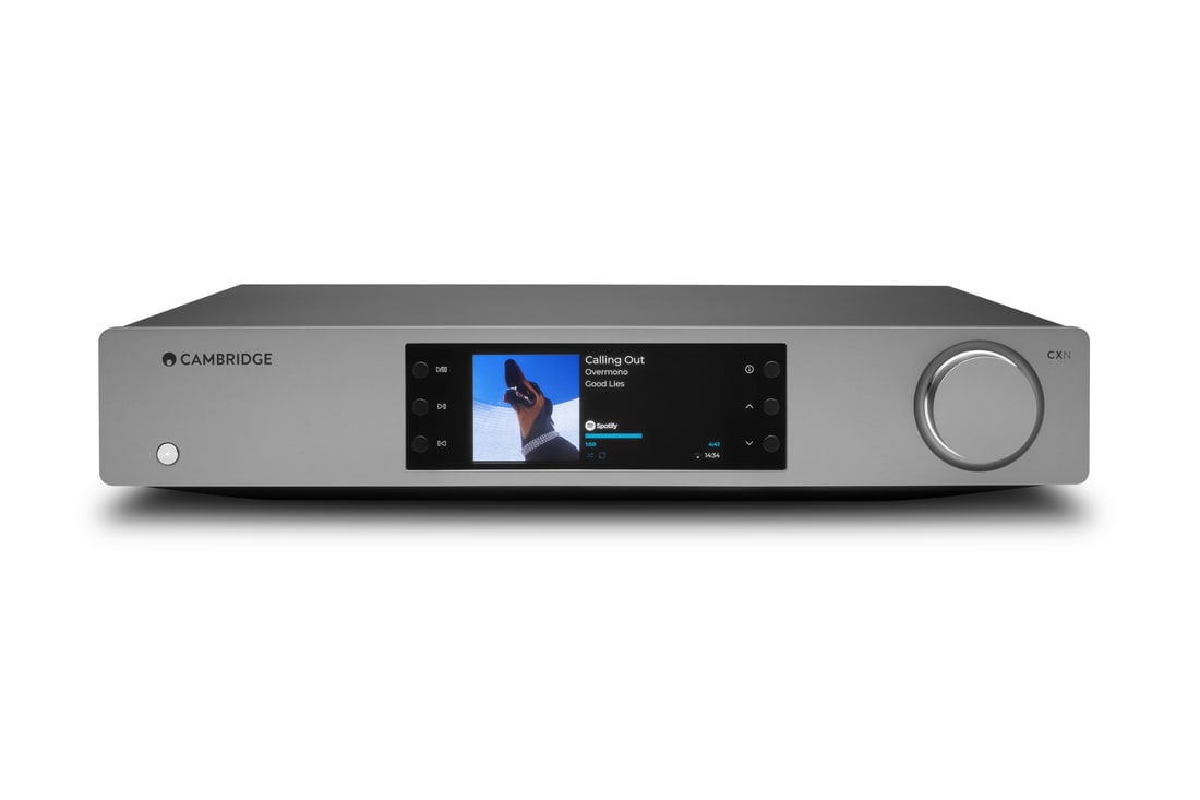 DNS and multiroom: why your streamer drops out at the worst timeMultiroom dropouts are rarely your Wi-Fi. Here's why DNS resolution quietly breaks streaming apps, and how to fix it for good.
- Parallel vs series IEM crossovers: why multi-driver in-ears sound so differentWhy do two IEMs with the same driver count sound nothing alike? The crossover topology is doing more work than the drivers themselves.
- Streaming a subwoofer's EQ filters: why your network player might be the bottleneckYour sub's miniDSP or app-based EQ can only act on a signal your streamer hasn't already mangled. Here's where network audio and bass management actually interact.
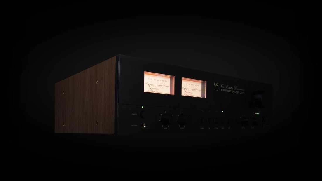 Amplifier gain structure: the setting that decides your noise floorGain mismatches between DAC, preamp and power stage quietly wreck dynamic range. Here's how to actually set gain structure instead of guessing at the volume knob.
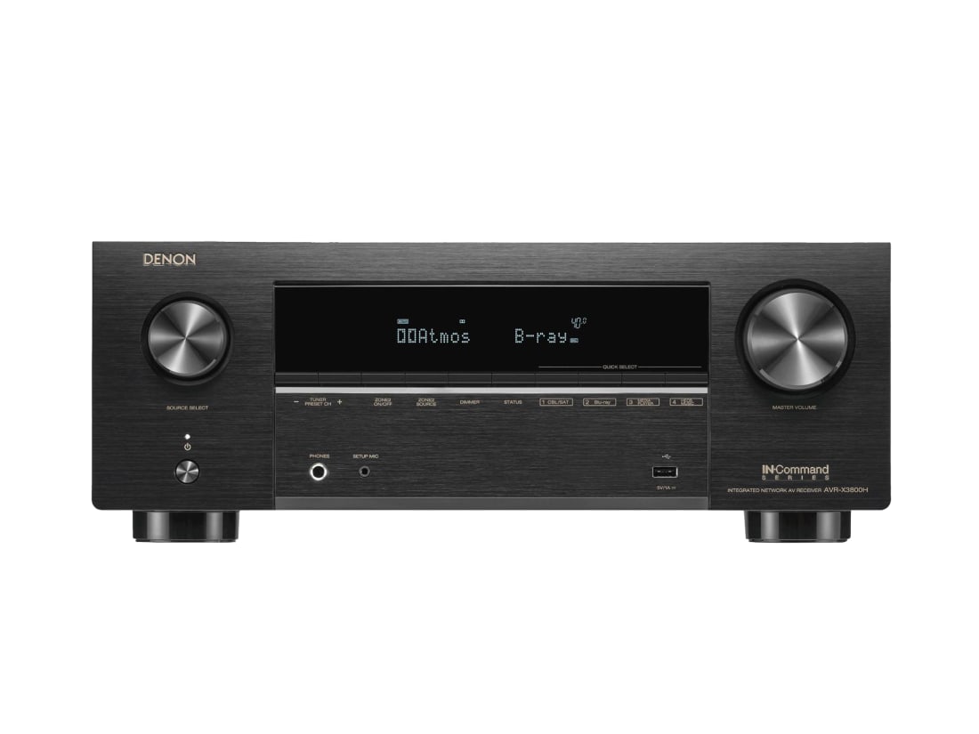 Bass management by the numbers: what your AVR's crossover and slope actually doCrossover frequency gets all the attention, but slope, distance settings and speaker size flags quietly decide whether your bass management works or fights itself.